Concentric swirl
Literature-led preferred concept
Rejected before detailed CADAssessed MEng Capstone Project
Race2Space MEng Capstone Project · 2024–2025
I worked within a 5-person student engineering team to design, manufacture and test a nitrous-oxide/HDPE hybrid rocket engine with a 600 N thrust target.
My principal technical responsibility was the oxidiser injector. I developed it from early literature review and concept down-selection through analytical sizing, CFD, CAD, design-for-manufacture and system integration, progressing to a final two-ring impinging injector. NASA CEA and MATLAB supported the shared propulsion sizing. I also contributed to the shared preliminary engine sizing and carried out early nozzle sizing before detailed nozzle development passed to another member of the team.
The completed engine was hot-fired and ignition was achieved, but leakage at the injector–chamber interface prevented the chamber from building to its intended operating pressure. Sustained combustion was therefore not established.
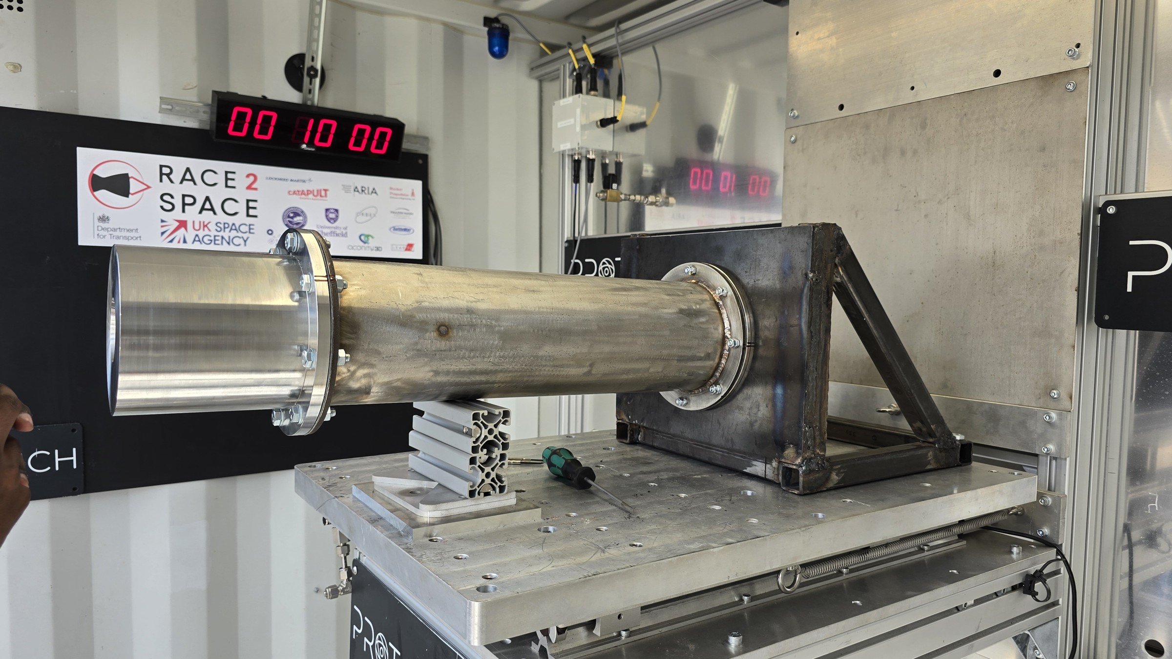
The project brief was not simply to analyse a rocket motor. The team was expected to take a hybrid propulsion system from preliminary calculations into detailed hardware, assemble it, integrate it with the Race2Space test infrastructure and attempt a static hot fire.
The engine used N₂O as the oxidiser and HDPE as the solid fuel. The common theoretical design was built around a 600 N thrust target, 5 s nominal burn, O/F = 7 and 33 bar chamber pressure.
The shared MATLAB file preliminary_calculations.m acted as the working engineering notebook for the theoretical design. It contained calculations and notes for propellant sizing, grain regression, chamber geometry, nozzle sizing and early injector work.
As component ownership became clearer, I took responsibility for the injector. I also contributed to the common engine sizing and performed early nozzle calculations before the detailed nozzle work moved to another engineer.
The completed engine shown at the top of this page is the hardware that emerged from that process. Later sections follow the same system from fuel stock and machined components through assembly, test-cell installation and post-fire inspection.
| Parameter | Design basis |
|---|---|
| Target thrust | 600 N |
| Nominal burn | 5 s |
| Propellants | N₂O / HDPE |
| O/F ratio | 7 |
| Chamber pressure | 33 bar |
| Initial fuel port diameter | 20 mm |
| Fuel grain overall diameter | 100 mm |
| Nominal grain length | 300 mm |
| Primary responsibility | Injector design |
Before the individual components could be designed, the team needed a common estimate of propellant demand, fuel-grain behaviour, chamber dimensions and nozzle requirements.
The first sizing step used the 600 N thrust target and an assumed specific impulse to estimate total propellant mass flow. At the initial design point, the model produced a total flow of roughly 0.235 kg/s, divided into approximately 0.206 kg/s oxidiser and 0.029 kg/s fuel.
The fuel grain was modelled as a single circular port, initially 20 mm in diameter, inside a 100 mm outer-diameter HDPE grain. Rather than keeping the geometry fixed, the MATLAB model stepped through the nominal five-second burn and updated oxidiser flux, regression rate, port diameter, remaining web thickness and fuel consumption.
That model was not a validated prediction of real engine performance. Its purpose was to give the team a consistent theoretical baseline that could then be challenged by CAD, manufacturing feedback and testing.
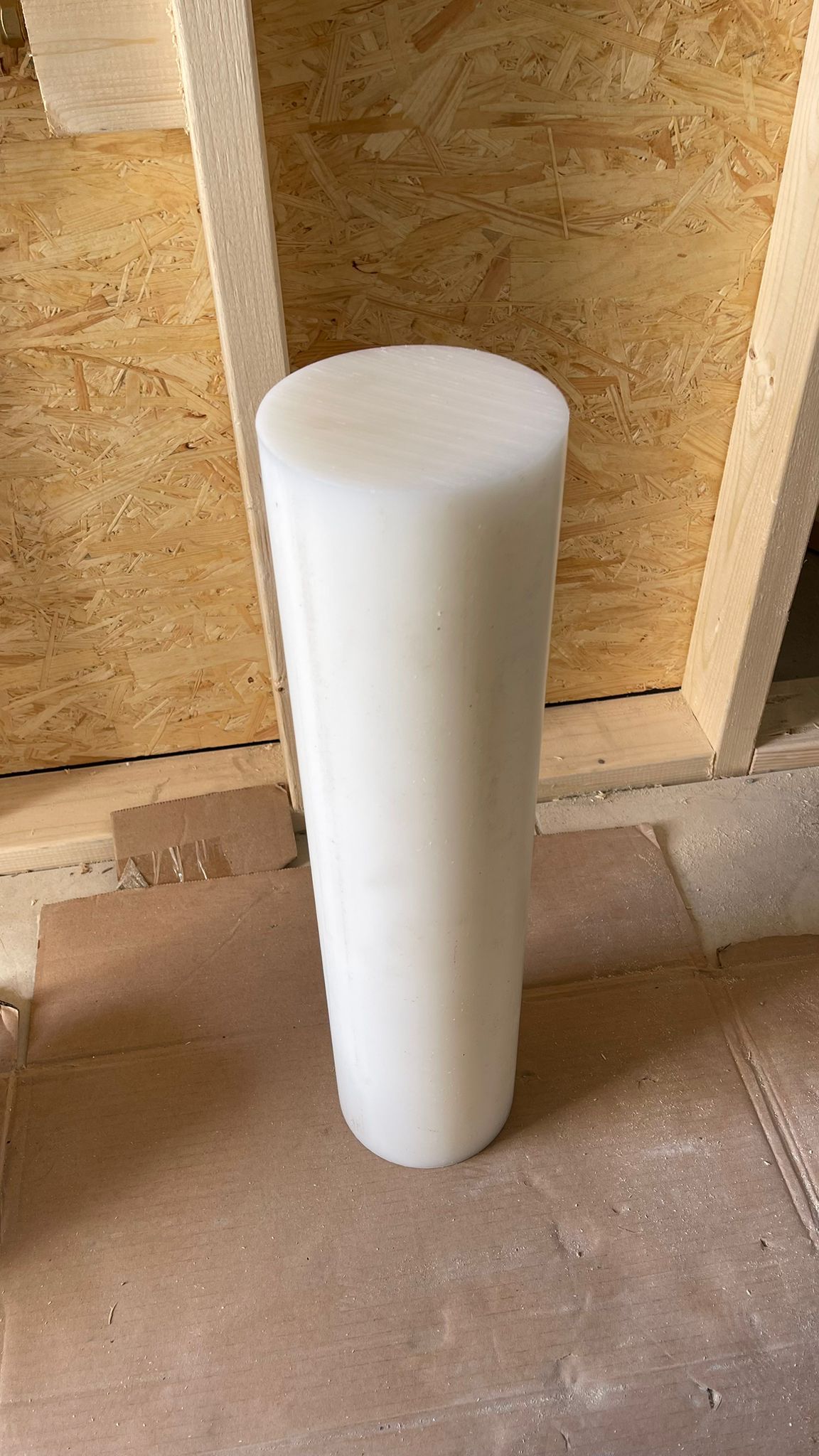
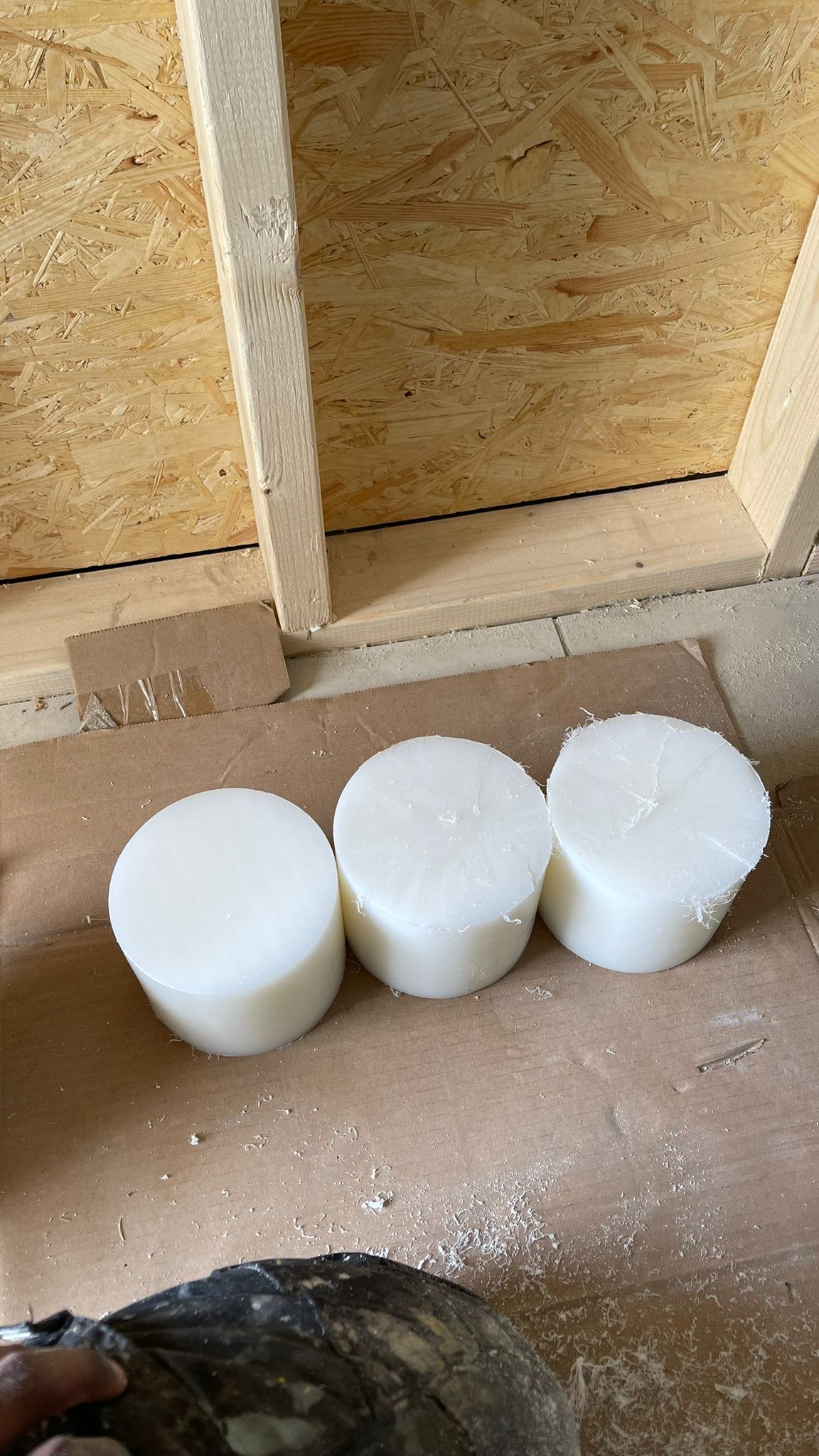
The photographs below show the HDPE stock used for the fuel grain before and after it was cut into shorter billets for further machining. They provide a physical reference for the 100 mm grain diameter used in the sizing model.
For this portfolio, I am rebuilding a small part of the original MATLAB logic in JavaScript so it can run directly in the browser.
The default state will reproduce the original project values. You will be able to adjust a limited set of inputs and see how the predicted fuel-port diameter and remaining web thickness change over the burn.
The point is not to create a general rocket-design tool. It is to show how the original assumptions interact and how the model informed the hardware.
NASA CEA was used during preliminary sizing to estimate combustion-gas properties needed by the chamber and nozzle calculations.
Several CEA runs were performed while the engine design was being refined. The surviving analysis files include a later parameter sweep across chamber pressures from 11 to 34 bar and O/F ratios from 4.8 to 7.
At the time, CEA was part of an iterative sizing workflow: choose a plausible operating point, obtain the required thermodynamic properties, carry them into the shared engine calculations and then continue developing the physical geometry.
A later audit of those files exposed an analysis-traceability problem that I discuss in the reflections section.
Although the injector became my main component responsibility, I also worked on the early nozzle calculations while the team was still establishing the wider engine design.
My work included area-ratio sweeps, conical and bell-nozzle length estimates, throat-length considerations and approximate nozzle-mass comparisons.
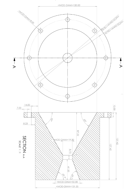
One useful example of the route from theory to hardware is the throat diameter. The preliminary model gave a value of approximately 19.33 mm, while the later detailed nozzle drawing shows a nominal throat close to 19.30 mm.
The numerical agreement above provides the comparison; the detailed nozzle drawing below shows the hardware geometry that followed. The final nozzle was not my individually owned component, so I treat it as system-level context rather than claiming detailed nozzle-design ownership.
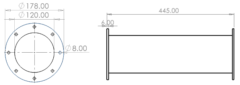
The chamber drawing below provides a similar link. The common sizing model used the 100 mm fuel-grain diameter together with liner thickness and internal clearance to establish a 120 mm internal chamber design basis. That 120 mm dimension later became a direct geometric constraint on the injector.
The injector had to meter and distribute oxidiser into the combustion chamber in a way that supported mixing and combustion while remaining compatible with the physical engine around it.
That meant the problem was larger than calculating an orifice diameter.
The injector had to satisfy several competing requirements:
provide useful atomisation and mixing;
remain within the chamber interface;
maintain an appropriate pressure relationship with the feed system and chamber;
coexist with the torch ignitor;
be manufacturable within a limited student budget;
bolt to the chamber and seal correctly;
and ultimately operate as part of an engine mounted to external test equipment.
The project became increasingly valuable to me as those constraints started interacting.
My initial preference was a concentric swirl injector.
The concept was attractive because swirl elements can provide good atomisation and mixing while avoiding an excessive pressure drop. NASA SP-8089 was one of the main references I used during this early stage.
The problem appeared when the concept was considered as a real manufactured part.
Small annular gaps, delicate swirl features and a more complicated internal geometry would have been difficult to manufacture reliably with the resources available to the team. The design was technically attractive, but too ambitious relative to the manufacturing route and budget.
The swirl concept was rejected before I committed to detailed CAD.
The next concept was a showerhead injector: a simpler plate containing multiple axial holes.
Its main advantage was manufacturability. It was easier to drill, easier to inspect and offered a relatively uniform axial flow distribution.
It became a useful baseline because it showed what could be achieved with low geometric complexity.
The trade-off was that it did less to promote primary atomisation than an impinging arrangement.
Again, this concept was down-selected through literature review, theoretical reasoning and manufacturing considerations rather than detailed CAD.
Following further study and discussion with the Race2Space external supervisor, the design moved to a like-doublet impinging injector.
Pairs of oxidiser jets were angled toward one another so that they collided after leaving the plate. The momentum interaction formed a spray sheet, offering more deliberate atomisation than the showerhead concept without returning to the complexity of the original swirl design.
This became the final architecture and was the only injector concept I took into full CAD.
Literature-led preferred concept
Rejected before detailed CADSimple manufacturable baseline
Rejected before detailed CADSelected architecture
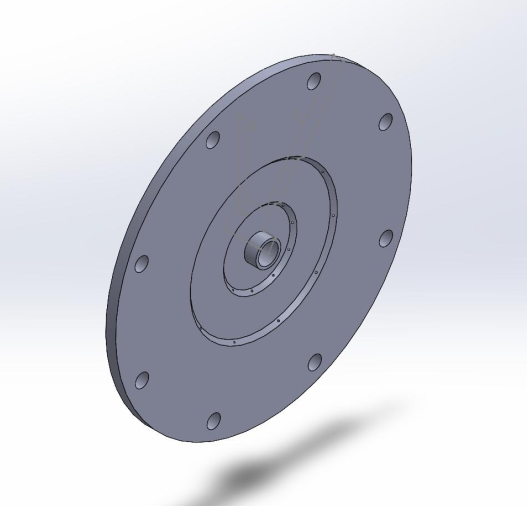
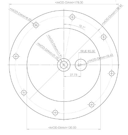
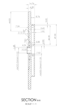
Analytical sizing → CFD → CAD → manufactureThe final design used a two-ring like-doublet arrangement with 20 orifices, each 1.5 mm in diameter, within the 120 mm chamber interface.
The injector was designed around a nominal pressure-drop target expressed as a fraction of chamber pressure, with the wider engine operating point centred on a 33 bar chamber condition.
The material selected was 304 stainless steel, chosen as a practical balance of availability, cost and expected performance.
| Parameter | Final design |
| Architecture | Like-doublet impinging |
| Ring count | 2 |
| Number of orifices | 20 |
| Orifice diameter | 1.5 mm |
| Injector/interface diameter | 120 mm |
| Impingement half-angle | 45° |
| Material | 304 stainless steel |
| Final manufacturing route | CNC + welded closure |
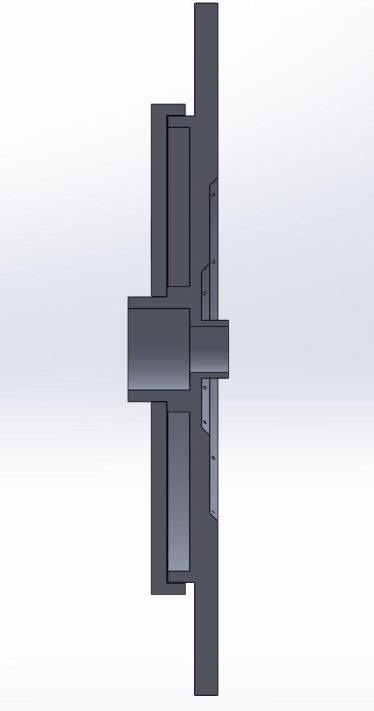
The CAD and technical drawings below show how the analytical injector work became a manufacturable component. The manufacturing photographs later in the page show the same design after machining and welding.
The final injector used a 45° impingement half-angle, even though the literature used during the project suggested smaller angles.
The submitted report mainly explained this as a packaging problem: the oxidiser jets had to clear the torch ignitor.
That was true, but it was only part of the decision.
The ignitor arrangement occupied real space at the injector/chamber interface. At the same time, a highly specific alternative angle could be easy to draw in CAD while being unnecessarily awkward to manufacture and inspect.
A geometry such as 32.5°, for example, might require additional setup, specialist measurement or extra technician effort for a relatively small local improvement.
The goal of the project was to design and manufacture a working engine. We did not have the budget to optimise every parameter independently.
Forty-five degrees:
cleared the ignitor;
was straightforward to define and inspect;
remained manufacturable;
produced acceptable behaviour in the comparative CFD;
and avoided consuming a disproportionate amount of the budget on one injector parameter.
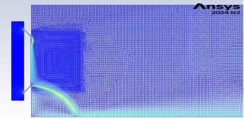
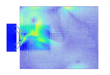
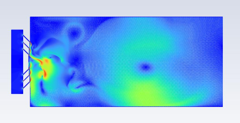
I used ANSYS Fluent to compare simplified 2D transient mid-plane models representing one-, two- and three-ring injector arrangements.
The CFD was primarily a comparative design tool. It helped answer which layout was worth manufacturing. It was not intended to prove that the full three-dimensional, multiphase injector behaviour had been resolved.
The one-ring arrangement became increasingly undesirable as the simulation progressed. The interacting jets did not maintain the desired central behaviour and the flow showed a stronger tendency to move toward the chamber walls.
That configuration was rejected.
The two-ring arrangement produced a more useful and stable flow direction toward the region occupied by the fuel grain.
Its simulated behaviour was good enough to continue into detailed design.
The three-ring model produced the strongest apparent spray behaviour of the three cases.
We still did not choose it.
The additional stepped geometry increased machining effort, material removal and the opportunity for manufacturing asymmetry. With small orifices, even relatively small deviations could change the balance between opposing jets.
The team therefore selected the two-ring design because it offered adequate predicted performance with lower manufacturing complexity and cost.
That became one of my favourite decisions from the project:
At the start of the project, the team expected additive manufacture to play a major role across the engine.
An on-campus facility had offered to sponsor manufacture, which meant complex metal geometry could potentially be produced without consuming most of the project budget.
That changed what we considered realistic.
The sponsored route later fell through.
Commercial metal additive manufacture was prohibitively expensive, so the team had to reconsider how the engine could actually be produced.
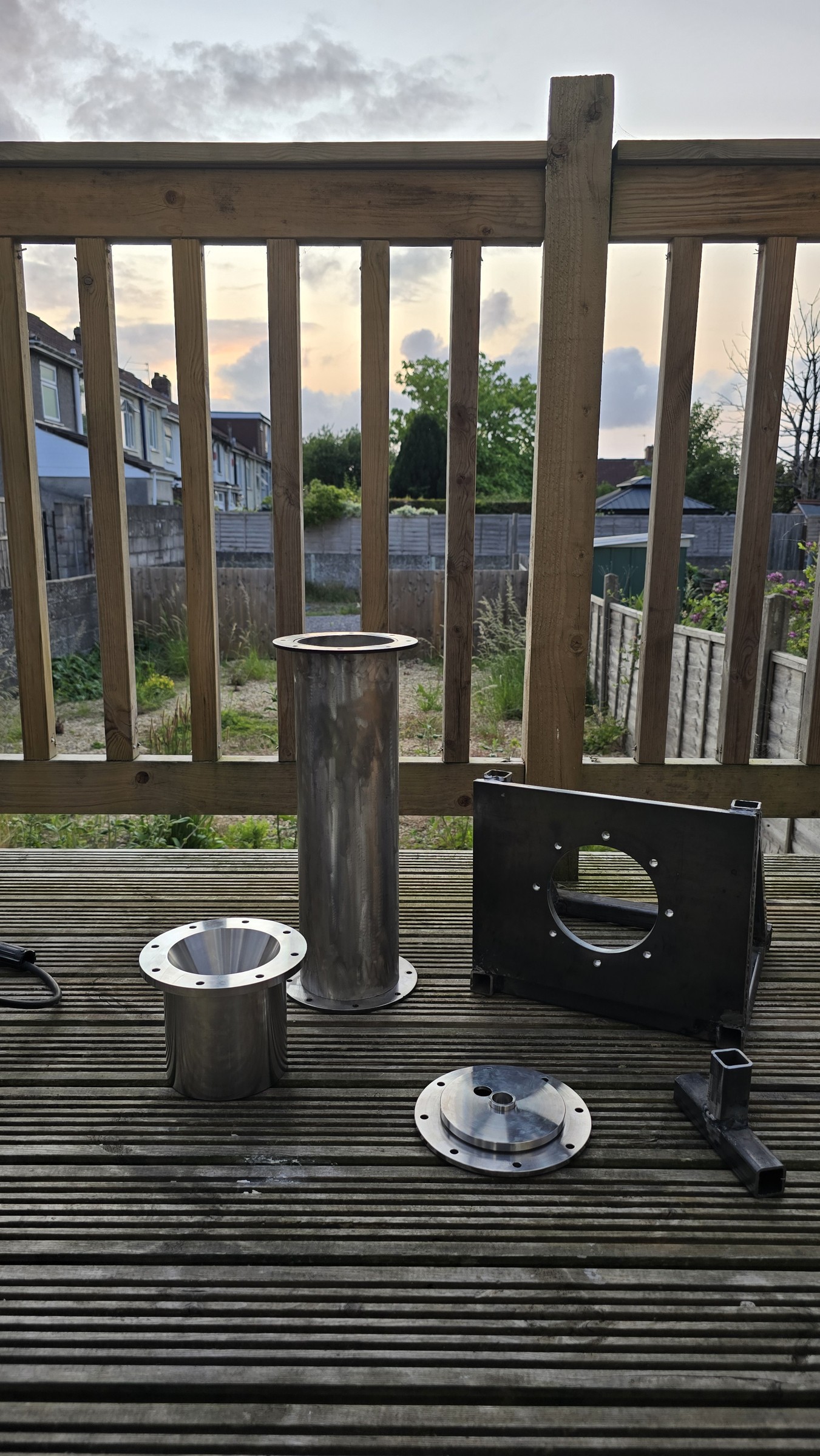
For the injector, we ultimately chose CNC machining in 304 stainless steel. CNC was not necessarily the cheapest possible process, but the geometry was complex enough that the cleaner and more controlled manufacturing route was worth the cost if it reduced defects.
The change in manufacturing process also changed the geometry.
An additively manufactured injector could have contained the internal oxidiser cavity within a largely monolithic component. Conventional CNC tooling could not reach the enclosed cavity.
The design therefore had to be opened for tool access and then closed again.
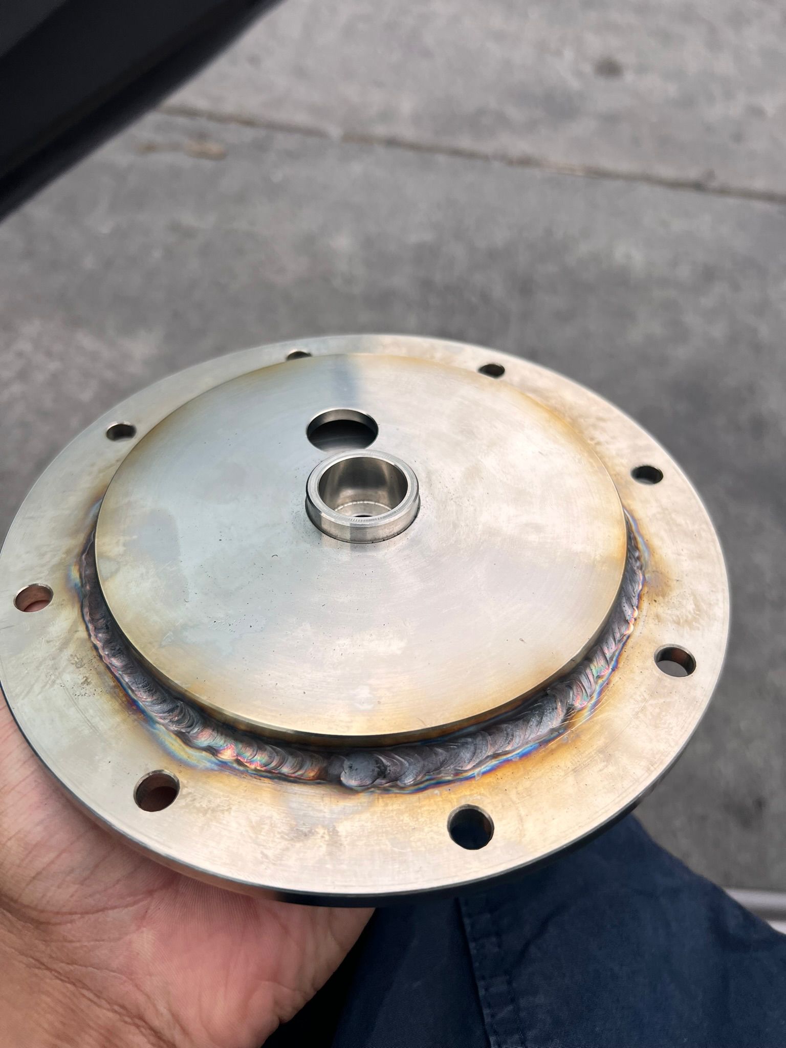
The rear section was machined separately and reattached using a circumferential weld.
The photographs below show that split construction in the manufactured injector, including the welded rear closure. The component overview and silent videos also show the chamber, nozzle and injector after finishing and during inspection.
That solved the access problem, but it introduced a new manufacturing risk: distortion and another potential leak path.
That trade-off became important during the hot fire.
component-inspection.mp4
polished-components-overview.mp4
As the manufactured components arrived, the project stopped feeling like a set of individual component reports and started behaving like a real mechanical system.
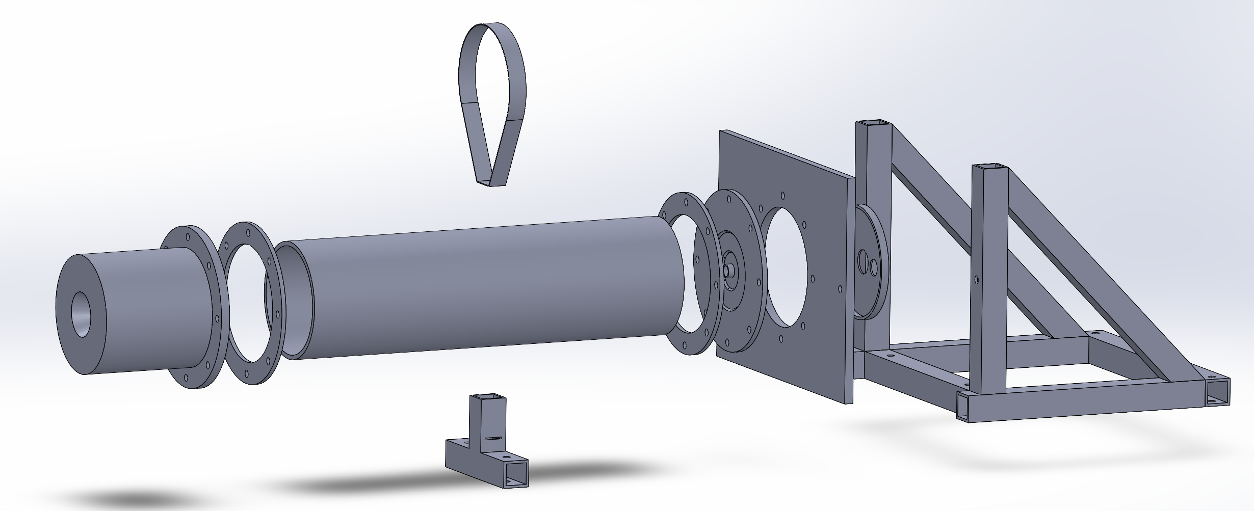
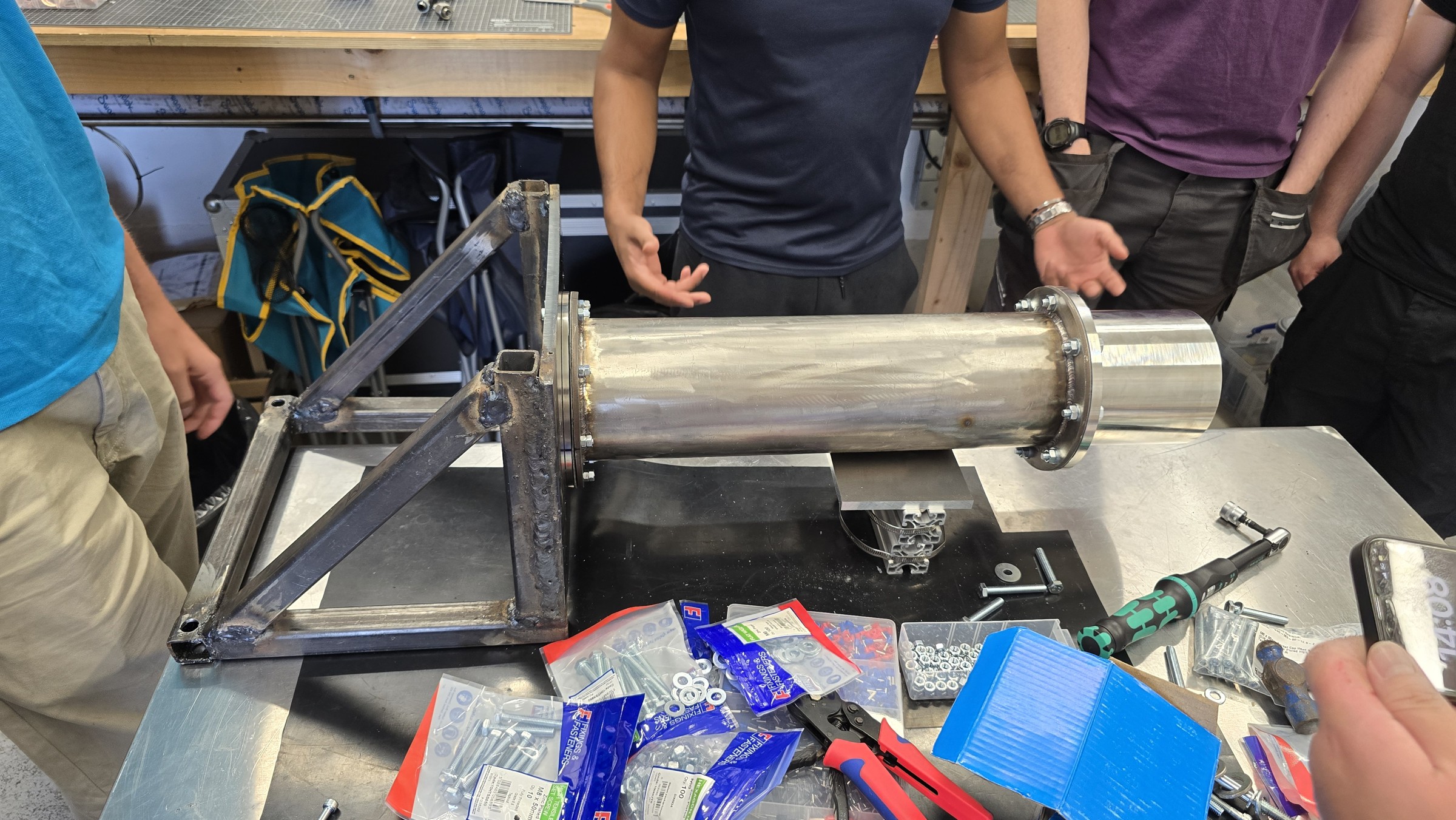
The injector had to connect correctly to the combustion chamber. The chamber, injector and nozzle then had to behave as one pressure-containing assembly. The complete engine had to interface with the test stand at Protolaunch - the company Race2Space had matched us with for the hot-fire test.
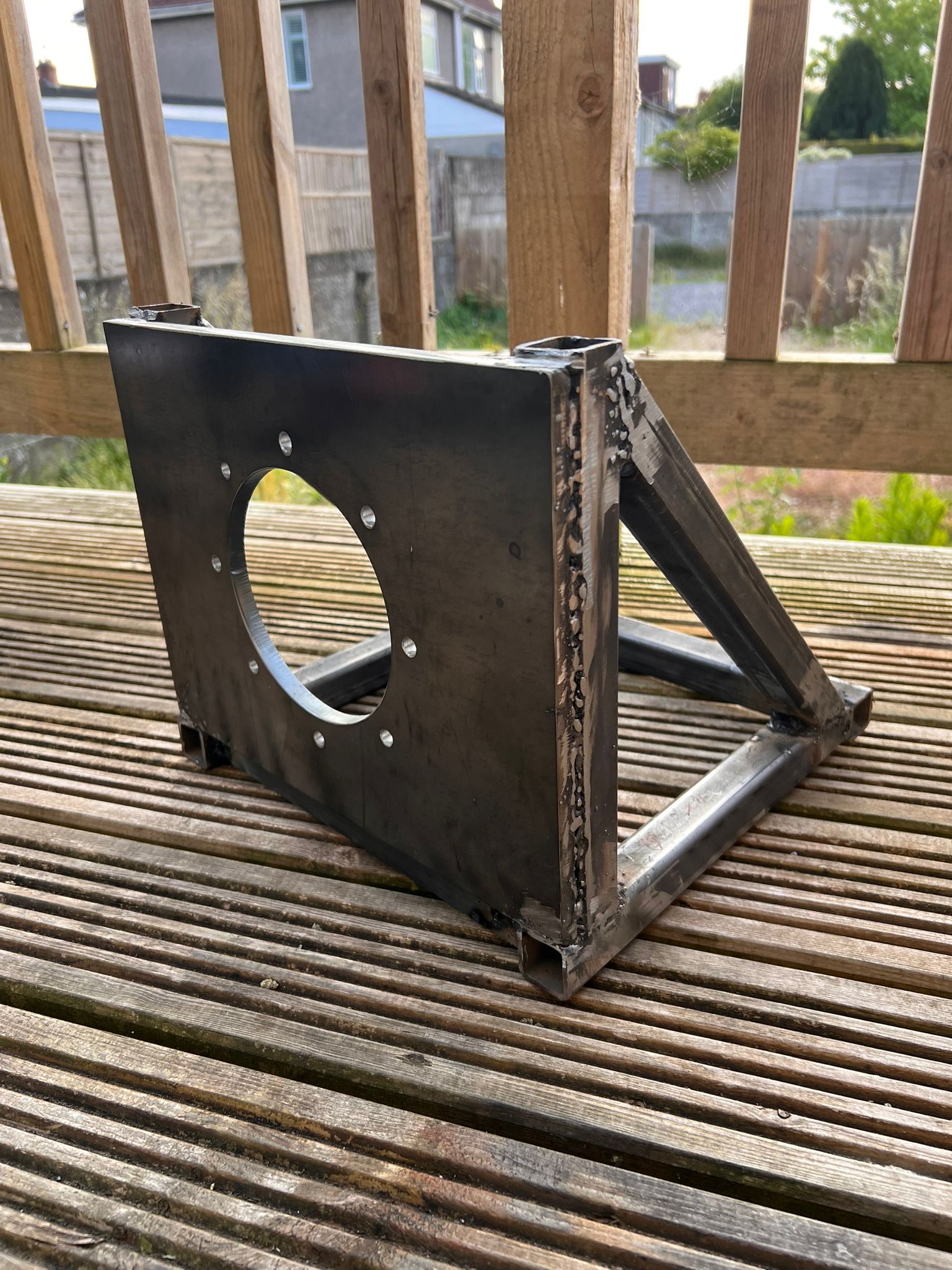
The exploded CAD view below shows the engine and test-stand relationship before assembly. The workshop photograph and short pre-test video then show the same system as physical hardware.
pre-test-engine-on-rig.mp4
This introduced requirements that had not been obvious when I was focused on internal injector flow:
The injector flange had to sit correctly against the chamber.
The sealing interface had to retain chamber pressure.
The torch ignitor had to coexist with the injector geometry.
The pressure relationship between the oxidiser feed and chamber had to make sense at system level.
The assembled engine then had to fit and behave appropriately on test infrastructure that belonged to someone else.
Late in the project, the team also revisited the intended failure behaviour of the system.
We considered how an off-nominal event could affect Protolaunch's test equipment and adjusted the system-level approach so that protecting the external test infrastructure took priority over preserving our own engine hardware.
This work happened much more informally than the earlier component analysis.
Calculations were performed collaboratively on paper, options were discussed as a group and the resulting decisions were summarised back to Protolaunch. It was real engineering work, but it did not leave the same clean design trail as the MATLAB files, CAD or component reports.
Quick route Next: Hot-fire outcome →The completed engine was hot-fired!
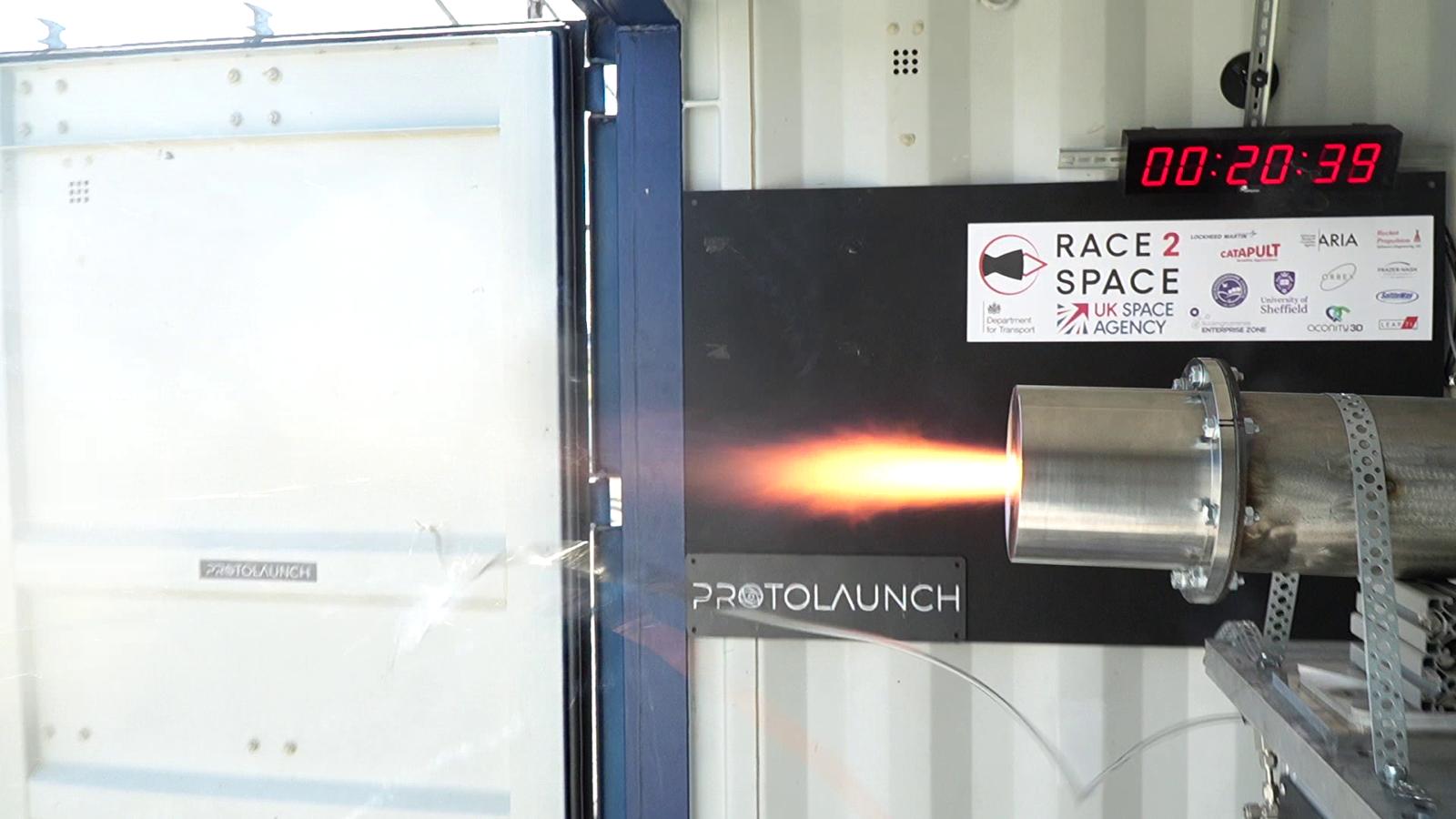
Ignition was achieved and a small visible flame was produced at the nozzle, but the engine did not transition into sustained combustion at the intended operating condition. Amongst ourselves we refer to it as the cough...
The hot-fire image captures that brief visible flame. Two silent post-test clips below show evidence from the hardware itself: first, burn evidence inside the fuel grain; second, the injector–chamber interface associated with the leak.
The limiting issue was leakage at the injector–chamber sealing interface.
The team's post-test assessment was that the injector flange had warped during welding, most likely because the component had not been adequately clamped while the welded section was being joined.
The distortion meant that the flange could not sit fully flush against the mating chamber surface.
The resulting leak prevented the chamber from building toward its 33 bar design pressure, so sustained combustion was not established.
The test therefore demonstrated an important distinction:
The injector had, admittedly, been manufactured for us free of charge. In hindsight, the free part found another way to collect its payment.
More importantly, the failure changed how I think about component design. I had spent a great deal of time considering orifice geometry, atomisation, pressure drop and spray behaviour. The flatness and integrity of a mechanical interface ultimately became just as important to whether the engine could function.
post-fire-fuel-burn-evidence.mp4
injector-chamber-seal-interface.mp4
The sealing problem was not an isolated event.
Looking backwards, the chain was:
sponsored additive route fell through → commercial AM became too expensive → injector moved to CNC → internal cavity required a split construction → split construction required welding → welding introduced distortion risk → flange warped → injector did not sit flush against the chamber → chamber leaked → pressure could not build → sustained combustion was not achieved.
That is one of the strongest lessons I took from the project.
My injector report received 68%, a 2:1 classification.
I do not think the mark belongs prominently on the portfolio page, but the post-submission feedback from my supervisor combined with my own thoughts was useful because it highlighted the gap between the engineering work that happened and the way I had documented it.
The largest issue was that the report was too component-centred.
It described injector theory, geometry, CFD and manufacturing, but it did not adequately explain how the injector fit into the wider engine.
By the end of the project, some of the most important work involved:
chamber and nozzle interfaces;
ignitor packaging;
sealing;
full-engine integration;
test-stand constraints;
and the system-level failure-mode discussion with Protolaunch.
That work existed, but the report did not capture it well enough.
The feedback also made me more critical of sections that were descriptive rather than quantitative. It is not enough to explain that a parameter matters or that one design is “better”. A stronger technical argument should make it clear where a number came from, what assumption produced it and what would happen if it changed.
To this end, the report should have included:
The original injector sizing relied too heavily on conventional single-phase flow relationships.
Nitrous oxide can flash as pressure falls across an injector. Under relevant conditions, density change, cavitation and two-phase choking can alter the mass-flow behaviour significantly.
My original report recognised this limitation and discussed more appropriate two-phase approaches, but I did not fully implement them into the final sizing.
If I repeated the design, this would be one of the first analytical improvements.
The injector discharge coefficient was estimated rather than experimentally measured before the design was frozen.
A dedicated cold-flow programme would have provided a much stronger basis for mass-flow predictions and could have exposed leakage, feed behaviour or unexpected losses before the hot-fire campaign.
The original CFD did not include a proper mesh-independence study.
That means the results were useful for comparative design guidance, but they were not sufficiently verified to support strong quantitative claims.
The 2D mid-plane representation also could not establish full-face symmetry or capture all of the three-dimensional jet interaction.
Cost influenced several major technical decisions, but the report did not quantify those trade-offs strongly enough.
The additive-manufacturing pivot, the choice of two rings over three and the decision to retain a simple 45° impingement geometry were all partly shaped by manufacturing effort and budget.
A stronger report would have preserved quotations, technician feedback, machining complexity and cost alongside the engineering calculations.
The final integration work should have appeared much more clearly in the report.
The injector was not just a flow device. It was a mechanical interface between the feed system and the combustion chamber, part of a pressure-containing engine assembly, and part of a test article mounted to external equipment.
The hot-fire outcome made that impossible to ignore.
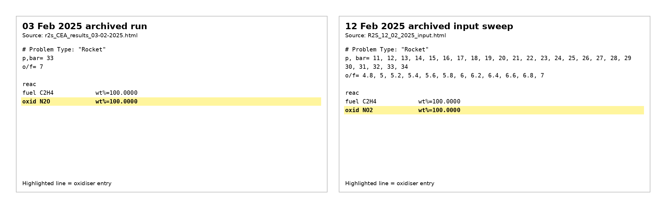
A post-project audit of the saved NASA CEA files exposed a configuration-control problem.
An early archived run correctly specified N₂O as the oxidiser.
Later parameter-sweep files were saved with NO₂ instead, and values from the later analysis history were carried into the shared design calculations.
The larger lesson is not simply that two chemical formulae were confused.
The project lacked a sufficiently controlled chain linking:
input deck → run identifier → output → approved design value → downstream calculation.
In future I would treat analysis files as controlled engineering artefacts rather than simply a collection of solver outputs.
The original injector work did not contain enough explicit numerical pass/fail criteria.
A stronger programme would define acceptance criteria before each test so that the result can be judged against a requirement rather than interpreted retrospectively.
If I started a second injector design cycle, I would not simply redraw the existing component.
I would rebuild the design and validation chain.
I would rerun the relevant NASA CEA cases using controlled N₂O input files, explicit run identifiers and a clear record of which output feeds each downstream calculation.
I would replace the simplified single-phase treatment with a more appropriate two-phase model and reassess the injector sizing across the expected operating envelope.
I would experimentally characterise the discharge behaviour and compare the measured result with the analytical model.
I still have the final injector CAD, so this is a realistic future personal project.
I want to model the complete injector geometry in three dimensions, perform a proper mesh study and see whether the full flow field supports the conclusions drawn from the original 2D comparison.
This is future work, not something I am claiming to have completed during the capstone.
I would treat flange flatness, sealing, ignitor packaging, chamber geometry and test-stand requirements as formal design inputs before the injector geometry is frozen.
A future drawing would not only define the nominal geometry. It would also make the functional manufacturing requirements clearer, particularly where interface quality affects engine operation.
For every major design change, I would preserve:
requirement → options → evidence → trade-off → decision → consequence.
That would make later technical reviews much stronger.
At the start of the project, I thought about engineering optimisation much more locally.
By the end of the project, I had a different perspective.
The three-ring injector produced the best CFD result, yet we opted for the two rings arrangement
Published guidance suggested a smaller impingement angle yet we used 45° for a mixture of reasons: anxiety, budget constraints, engineering concerns etc.
Additive manufacture offered cleaner internal geometry, yet we chose CNC in the end.
None of those choices make sense if 'optimisation' means maximising one technical metric.
They make much more sense if optimisation means finding a design that gives the whole system the best chance of being manufactured, integrated and tested within the constraints that actually exist.
The project also taught me that engineering confidence has to survive every transition:
theory → code → CAD → manufacture → assembly → test → analysis of the result.
The injector could be theoretically sensible and still fail to support engine operation because the flange was not sufficiently flat to seal against the chamber.
The unavoidable fact is that the engine did not demonstrate sustained operation at its intended design condition.
But the project did progress through:
preliminary propulsion sizing;
fuel-grain and chamber calculations;
early nozzle sizing;
injector concept development;
analytical injector sizing;
CFD comparison;
detailed injector CAD;
technical drawings;
manufacture;
engine assembly;
test-stand integration;
and hot-fire ignition.
The test then exposed a manufacturing/interface problem that the earlier component-level work had not controlled well enough.
For me, that makes the project more valuable as an engineering case study, not less.
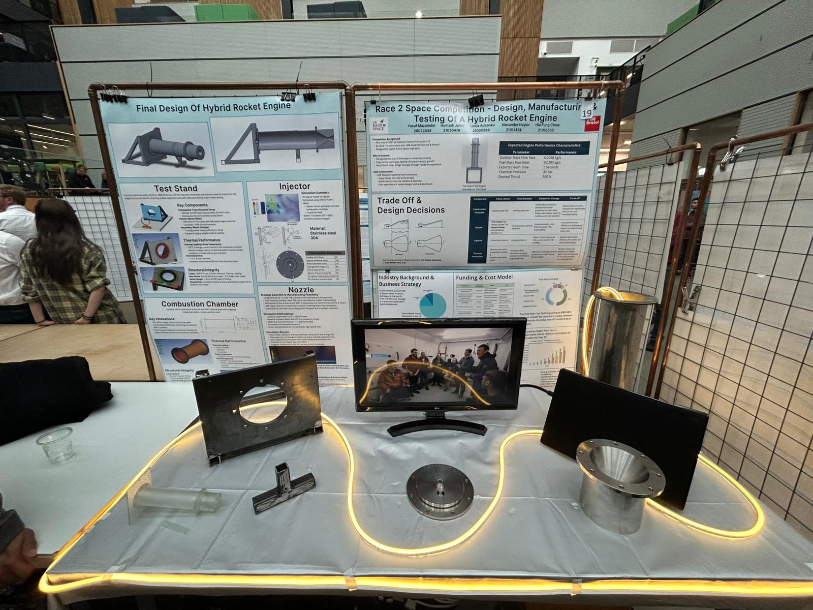
A Degree Show photograph at the end of the page provides a final view of the manufactured hardware in the wider project context.
The detailed injector report contains the original literature review, analytical sizing, CFD comparison, CAD development, manufacturing discussion and the first set of design reflections.
The historical project repository also contains the surviving MATLAB scripts, saved plots and part of the analysis history.
The following were among the main technical sources directly used during the injector and propulsion work: